


Levitating Globe Teardown, Part 2
Part 1 of this article was really more of an extended (and cynical) product review. In this part of the article, I actually take things apart (sometimes a bit more suddenly than I meant to) and show you some innards.First the globe. I knew there was a magnet in there someplace, because it's obviously plastic and it also attracts metal. I had intended to gently part the globe at the glue bond along the equator. I started by trying to gently flex the thing on my work bench, hoping that the glue was significantly more brittle than the surrounding plastic. I was wrong.
The picture shows the remains of the globe. In the lower right of the picture can be seen the circular black plastic magnet holder, and the magnet itself. The magnet was inside the holder, and the holder was attached to the "north pole" of the globe with a plastic rivet. The magnet is a rare-earth magnet, and is the biggest one I've ever seen in a piece of consumer equipment. It's 30mm diameter by 12mm thick. The only bigger ones that I've seen have been pole pieces for motors in aerospace applications, although I'm sure there are some electric motors out there that can sport large magnets, too.
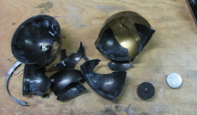
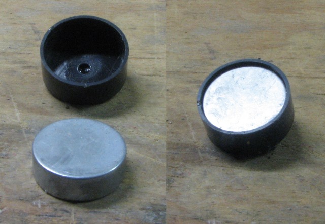
The big magnet is a large part of why this relatively cheap toy can levitate a globe a good half an inch below the head: the magnet starts pulling into the head from about an inch away, and without its globe, plastic holder and rivet, the thing hangs onto the head piece to a scary degree.The picture below shows the detail of the magnet and mount, and the magnet fitting into the mount.
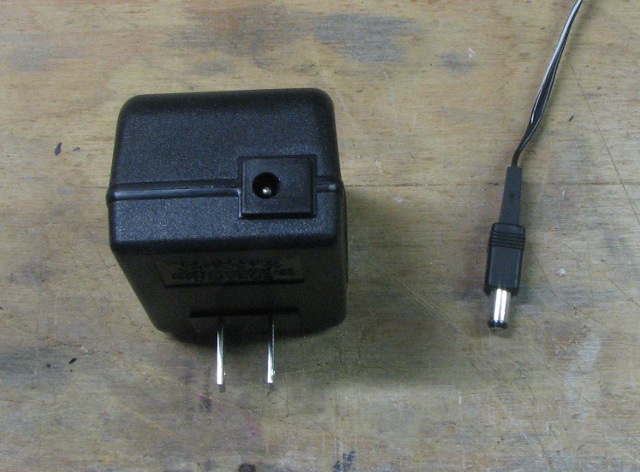
The arrangement of the power cord is one I haven't seen before. Instead of putting the cord on the wall-wart, the cord is on the base and that plugs into the wall wart. The wall wart is rated for 24V at 5VA. It doesn't say, but the circuit design implies that it is an AC adapter.
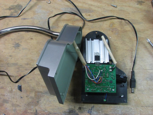
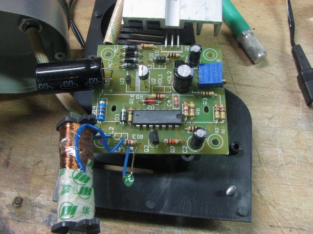
With all the pieces of globe removed, I took the base apart. The picture shows the copper side of the circuit board, the transistor in its heat sink, and the wires going up into the arm to the head. The circuit board has four holes and there are four standoffs in the base, but there are only three screws -- ain't top-notch workmanship great?
This picture shows the top of the circuit board. The upper left corner has the four diodes for the power supply. I'm assuming that U2 is a 5V or 3.3V regulator. Given the scarcity of resistors and capacitors on the board, that 16-pin DIP is a microprocessor, not a quad op-amp. Clearly someone was concerned that a potential competitor might figure out which 16-pin microprocessor was used here -- although the program to be found inside would be the more critical intellectual property, in my opinion.
The fact that this thing is microprocessor driven makes the performance of the control loop inexcusable, in my humble opinion. Yes, it's just an executive toy, but it could be a really good working executive toy with just a bit more effort!
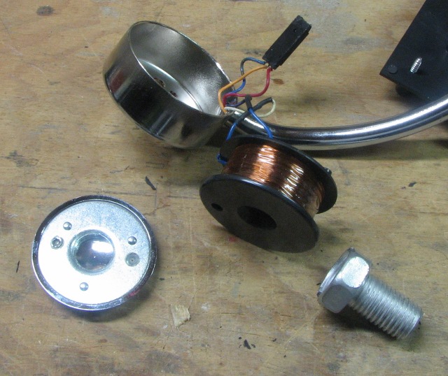
The large coil that you see in the lower left of the picture is a coil for turning the globe. If you refer back to the picture of the shards-o-globe you'll see a magnet embedded in one half -- that magnet, plus this coil, are there to make the globe spin. It didn't really work right and I don't much care anyway, so I'm mostly ignoring that function.This picture shows the arm mounting from below. The arm is held into the top of the base with a nut, and there are flats on the arm (next picture) that keep it from rotating. The arm is hollow, and there are five wires leading out of it to the circuit board.
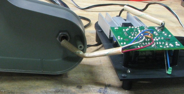
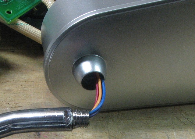
This picture shows the arm out of the base. You can see the flats that hold it in alignment. I think this is clever design: for a very little bit of money spent in manufacturing, they've made sure that the arm gets put together right and always stays in place. I may be making snarky comments about this gizmo, but in some ways the design itself is well thought out.
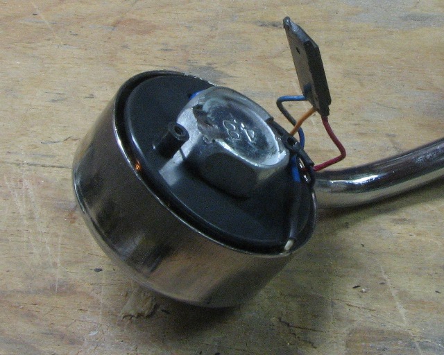
Here's a picture of the head, with its cover removed. The cool high tech magnetic core is -- a bolt! A crummy bolt. That black thing on top of the bolt is, I'm sure, a hall sensor. I'm not sure how the hall sensor reads the position of the magnet when its readings are confounded by the current flowing through the electromagnet, but I plan on gathering data for part 3 of this series.
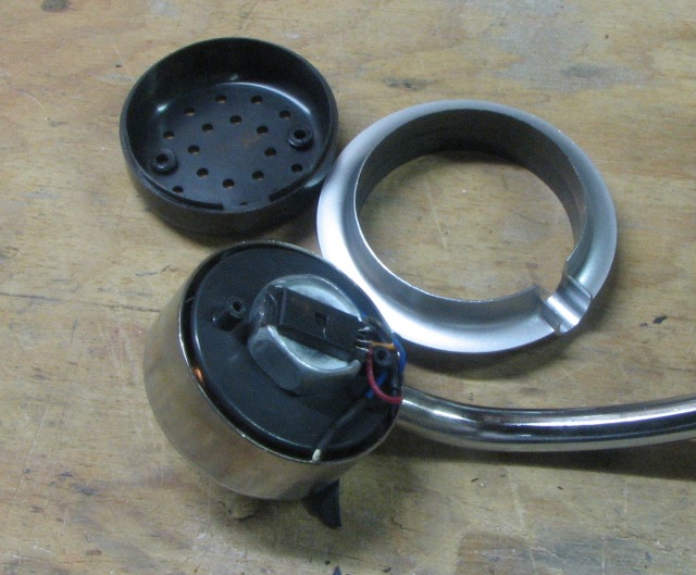
Here's a view of the head with the hall sensor pried off the bolt. Someone actually took the trouble to run the bolt through a milling machine, or the paid someone to do a pretty good job with a file.It may not be apparent from the pictures, but the housing for the head piece is stamped out of steel and chromed. I'm sure that this helps concentrate the magnetic lines of force from the head and thus gives a longer 'hang' distance.
And finally, here's a shot of the electromagnet completely disassembled. While the top part of the head is plastic with flashed-on chrome, inside is a plain flat stee part, threaded for the bolt and keyed to the head stamping with dimples that fit into matching holes in the stamping. Here again, I'm sure that the reason this is made of steel is to provide a path for the magnetic flux.
So with the exception of finding a bolt (fer cryin' out loud) as the central part of the magnetic circuit, I haven't found any surprises at this point, although there's a lot of nifty detail.
Careful inspection of the placement of the "ventilation" holes in both the base and the head will reveal that whoever designed this thing believed that if you ventilate the bottom of a hot part then you're all set -- even if you haven't done anything about the top. The directions warn about heat, but if they'd really wanted to get rid of the heat there should be some mechanism for venting air out of the top of the base and head.
I was somewhat surprised at how fine the wire is in the head. This is interesting. I'm not sure what the designer was thinking -- the wire is fine enough to impact the difficulty and expense of winding the head, yet the whole thing is powered off of a 24VAC wall-wart. Had they designed the system to operate off of 12 volts they could have doubled the wire area and halved its length, making it less likely to break while winding, and requiring fewer turns to wind.
In part 1 I mentioned that the electromagnet is unidirectional. It always acts to attract the magnet, which means that the magnet always hangs below the unpowered equalibrium point. This is both borne out and explained by the single power transistor in the circuit -- by designing the electromagnet to only attract, the manufacturer can shave some pennies off of the price of the toy, and make a bit more profit, or sell more units. The alternative would be an H-bridge, which would require at least four active devices and a great deal more attention to circuit detail; it is not surprising that the manufacturer chose as they did.
After I broke open the globe, and even before I started disassembling my toy to see how it ticks, I found the temptation to play with that magnet irresistable. In fact, this led to me getting this whole article out a bit earlier than I intended to, because I'm having so much fun!Just about anything that is roughly the weight of the globe, and that fits under the arm, can be levitated. Spools of wire, felt pens, blocks of wood -- you name it. A troll doll would be perfect, or maybe the right size of Smurf, or a plastic dinosaur. Here's a shot of various things I had lying around my bench, happily levitating.
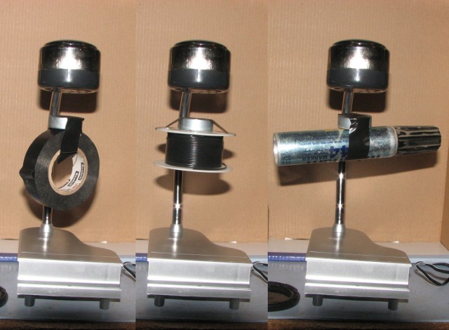
You can even stick the magnet inside of something ferrous, if the walls are thin enough.

You could almost stop here, and have fun with this thing. Levitating globes are old hat these days, but how many people do you know who have a levitating tea tin in their office? (Please don't ask me why I find a levitating tea tin to be compelling -- it just is, and I don't think I want to know why).
One note of caution if you should start playing with this toy in this manner: the magnet is strong enough that small children should not play with it without supervision. This particular magnet is not quite strong enough to pinch adult fingers, but I have gotten myself trapped between a larger version of it and a hunk of steel, and the experience was painful. I'd let kids play with it, but only if I were standing by keeping an eye on things. You know the kids around you: use your own judgement.

In part 3 I'm going to take the base off of this thing again, and see if I can get some measurements of the attractive force of the magnet and the voltage from the hall sensor as the electromagnet current and the proximity to the magnet are varied. I'll also find out if the transistor is operated in its linear region or if it is pulsed. That information should be enough that I can then launch on an effort to build my own controller for this and experiment with different control rules.
- Comments
- Write a Comment Select to add a comment

I can't agree with your comment about the fine wire, however -- the reason is that the other elements in the circuit (transistor + cord going to the wall power supply) are more efficient at higher voltage low current. 12VDC makes poor use of MOSFET silicon die area; your most cost effective MOSFETs per unit die area are probably in the 40-60V range, and not the 20-30V range where you have to waste a lot of the voltage in design margin. In my experience the best system voltage choice is probably in the 36-48V range -- just about the max voltage before exceeding ELV guidelines.

Stuff like this tends to be copies of last year's stuff like this, which tends to be copies of the year before. Given that I wouldn't be surprised if the pass transistor is a junction transistor rather than a FET. In that case the 0.2V drop of a cheap junction transistor, or worse the 1-ish volt drop of a cheap Darlington would certainly drive you in the direction of a high voltage rail.
I'll try to remember to figure out what the transistor is in part 3.

"
I'm not sure how the hall sensor reads the position of the magnet when its
readings are confounded by the current flowing through the electromagnet,
but I plan on gathering data for part 3 of this series.
"
Just my naive guesses ...
By knowing a priori the field produced by the electromagnet (function of the
current) and having a model of how it is perturbed by the permanent magnet,
and given the object and environment wont perturb it too much, it seems to
me a control algorithm can work without trying to 'cancel' the permanent
magnet field actually mixed in the hall sensor readings.
Another idea: is it possible the electromagnet gets switched off allowing
the hall to read only the permanent magnet field? I do not have a clear
intuition of the timing required here (ie. how long does it take to the electromagnet
field to fully collapse and then rebuild + how long does it take to read the
hall versus permanent magnet acceleration and distance).
It would be interesting to play with different permanent magnets or selfs to see
how the system behaves, and get insights into the control algorithm.
Waiting for the next part for answers /guesses :)
I'm pretty sure that the coil has sufficient inductance that if you waited for the current to drop off and then measured that you'd hear audible singing from the thing, and possibly that you'd get excessive warming of the pole pieces from eddy current losses.
On the wire size question, I would say that you want to keep the wire as small as possible so that it is as close as possible to the pole piece (bolt). When you use a smaller wire it has more resistance so you need more volts to get the current for a given field, hence using 24V.
That's not how solenoids are designed. Distance to the pole piece doesn't matter too much. What matters is the total number of amp-turns. Whether you use 100 turns of 28ga wire or 200 turns of 31ga wire (which has half the cross-sectional area and hence can support half the current) doesn't matter; it's the same total copper volume (assuming copper packing efficiency is the same, which is true for wire sizes that aren't too large or too small). You select the number of turns to match it with the coil voltage (as you noted). Good automated winding systems use a tensioner to ensure consistent winding.

http://www.reddit.com/r/ECE/comments/2kofek/secondorder_systems_part_i_boing/
To post reply to a comment, click on the 'reply' button attached to each comment. To post a new comment (not a reply to a comment) check out the 'Write a Comment' tab at the top of the comments.
Please login (on the right) if you already have an account on this platform.
Otherwise, please use this form to register (free) an join one of the largest online community for Electrical/Embedded/DSP/FPGA/ML engineers:


