


Feedback Controllers - Making Hardware with Firmware. Part I. Introduction
Introduction to the topic
This is the 1st in a series of articles looking at how we can use DSP and Feedback Control Sciences along with some mixed-signal electronics and number-crunching capability (e.g. FPGA), to create arbitrary (within reason) Electrical/Electronic Circuits with real-world connectivity. Of equal importance will be the evaluation of the functionality and performance of a practical design made from modestly-priced state of the art devices.
- Part 1: Introduction
- Part 2: Ideal Model Examples
- Part 3: Sampled Data Aspects
- Part 4: Engineering of Evaluation Hardware
- Part 5: Some FPGA Aspects
So, in a sense, this is a DSPRelated, FPGARelated & ElectronicsRelated Blog with a bit of Feedback Control thrown in. There will not be any heavy-duty mathematics in this Blog as Messrs Laplace & others have reduced most of the required maths to algebra and then MATLAB/Simulink handles that bit so that we can spend our time primarily looking at pictures of systems and responses.
Closed-Loop vs Controller Applications
Although the focus of the study will be on a closed-loop hardware emulation application, consideration will also be given to the use of developed controller technology for wider applications.
Emulating Hardware - A Philosophical Question
Q. Given a 2 terminal block containing an arbitrary circuit, can we emulate that using an ideal computer connected to an ideal amplifier for connectivity to real-world applications ?
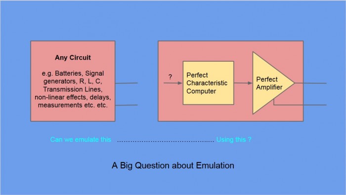
Fig 1. Posing a question about circuit emulation.
A. For a simple example circuit consisting of a voltage source V1, a source impedance Z1, the circuit can be emulated for any load L if, the output of the ideal amplifier is set as VL= V1 - Z1*iL, where iL is the measured current in the load L.
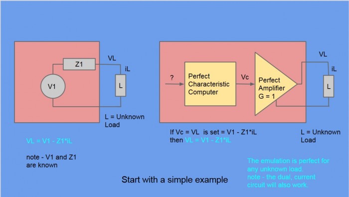
Fig 2. Achieving circuit emulation for a simple example, utilizing feedback control.
It is noted that this voltage feeding, current measurement emulation arrangement is not the only possible solution topology, nor is it claimed to be the best solution.
A Key Characteristic of Controllers for Closed-Loop Applications - Latency is King
It will be seen that latency is one of the defining limitations in the performance of closed-loop control applications. This is particularly true for the circuit emulation application because we require more than speed, stability and convergence to zero error. In the circuit emulation case we require precise behaviour at every instant in time, which goes beyond a well-behaved zero-error convergence.
The ability of say, an ADC, FPGA and DAC to run with very high throughput is thus of secondary importance to getting controller outputs with minimum time-delay/Latency.
Elements of a Practical Solution for Performance Evaluation
A technology evaluation design has be made to allow the functionality and performance of circuit emulators and low-latency controllers to be evaluated. Key device technologies include :-
- LinearTech(Now ADI) SAR ADC's and DAC's
- TI,Maxim and ADI amplifiers
- INTEL/Altera Cyclone V FPGA (Maybe Cyclone 10 GX later).
Technical Tools that are being used during project development
- LTSpice and TI TINA Spice simulators for circuit performance testing
- Altium Circuit Studio - For schematic design and PCB layout
- Altera Quartus Prime - for FPGA development
- MS Visual C# - for PC GUI applications
- MATLAB/Simulink for s and z domain designs & simulations
Expectation of Functionality and Performance
At the time of writing this, no FPGA code has yet been written to perform the closed-loop controller functions.
However, a previous design made some years ago using an ADI Sharc DSP, SAR ADC and DAC did perform over and above the technical requirements, for a telecom standards test instrument.
The expectation is that the FPGA based design will provide for higher frequency and higher complexity emulation and controller performance. The limits and limitations are to be discovered.
More detail on that, to come.
Coming Next .....
Next up will be a look at some specific circuits to be emulated, along with the ideal controllers needed for their implementation. Examples will be developed in MATLAB/Simulink and then the non-ideal performance of ADC's, DAC's & Control Law computers will be introduced.


- Comments
- Write a Comment Select to add a comment
To post reply to a comment, click on the 'reply' button attached to each comment. To post a new comment (not a reply to a comment) check out the 'Write a Comment' tab at the top of the comments.
Please login (on the right) if you already have an account on this platform.
Otherwise, please use this form to register (free) an join one of the largest online community for Electrical/Embedded/DSP/FPGA/ML engineers:


