


Trying to make the simplest VPP voltage switch for micros
I'm trying to make myself the proper voltages for VPP output using the fewest number of parts that are readily available in store (particularly from sayal electronics ( http://www.sayal.com ) ).
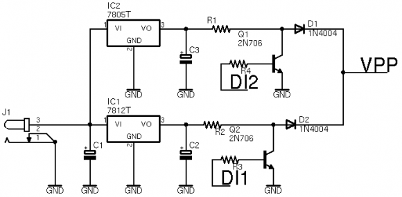
Below is my circuit attempt except for Q1 and Q2, I plan to use 2N3904 and 10K for resistors to start. C1, C2 and C3 will be 22uF electrolytics. DI1 and DI2 will be connected to outputs of a 74HC573 octal flip-flop IC. J1 connects to a voltage between 12 and 18 and the source will have a C+ style plug.
I think my design is a little goofed and I feel heat will generate, but I need help in making this design proper and not over-worked so that most microcontrollers will be happy with the VPP voltage I'm feeding it.
What can I do to improve this circuit?
You don't say exactly what you're trying to do. I presume you're trying to raise a logic/programming line to +12V to program an EEPROM.
If that's the case, you can toss most of that circuit (which has numerous issues) and just use a diode to connect +5v to the VPP pin. Also connect the VPP pin to a jumper that bridges to 12V when you want to program the board. See, for example, this Microchip app note.
If you need to do it programmatically, consider something like the MAX662A, which is designed for exactly that application.
Yes, that's exactly why I need the 12V, to program the code EEPROM in the AT89 series of microcontrollers so that it contains my code.
...and just use a diode to connect +5v to the VPP pin....
Ok, does the diode need to be zener with cathode connected to VPP? and what about a series resistor to limit current?
...consider something like the MAX662A...
Sadly that part isn't locally available.
I'm going to figure out a simpler way if possible
A zener diode is usually used for voltage regulation. All you need is reverse blocking (of 12V), and minimum forward voltage drop (from 5V). A Schottky diode with the cathode tied to the VPP pin is recommended. Current limiting isn't necessary as the VPP pin will draw only the current it needs. The resistor and capacitor shown in the Microchip app note is a simple RC filter/pullup that keeps 5V (less the diode forward voltage drop) on the VPP pin during normal operation (on PIC/8051 processors VPP high is the typical run state if no external memory is present.) The circuit would probably function fine with just 5V tied to the anode of the diode, but the RC filter provides a little more isolation between the 12V programming voltage and the rest of the circuit.
Unless the processor you're using has a bootloader capable of programming itself and you plan on having the processor program itself in the field, it is usually more cost-effective to provide the programming voltage from an external circuit (eg a lab power supply or programming pod) when programming the device during manufacturing/test.


