


Filter-Amplifier circuit for Low Voltage I/P circuitry.
Hello,
I'm designing my first ever circuit for a hobby project. I've a sensor that outputs in mV and a controller with ADC. The ADC is 16 bits, VDDA = 3.0 V, Temp = 25 °C, fADCK = 1.0 MHz. Since the sensor voltage that is fed is to the controller is low I'm in a predicament! Should I use a low pass filter or a band pass filter in this application? Do you have a circuit that I can relate to? Any advice is appreciated. Thanks :)


What's the sensor output spectrum of interest? (e.g. DC-1kHz, 1kHz-10kHz?) That will tell you what you care about; oversampling and filtering out unwanted frequencies will help you reduce noise content... although sampling at 1MHz and filtering can use quite a bit of compute power, and it may be better to put in analog filtering first so you don't need just a high sampling rate.
Since the sensor voltage that is fed is to the controller is low I'm in a predicament!
Then amplify it, if necessary. If you want to minimize cost, you're probably better off with a 12-bit ADC and a x10-20 gain amplifier. If you want to minimize time-to-a-solution, use what you have now.

Questions you need answers for:
- How often do you need the data (alternately, what bandwidth do you need)?
- How accurate is the sensor supposed to be?
- What is the sensor's bandwidth?
- How accurate do you need it to be (in mm or degrees Celcius or whatever)
- What voltage accuracy does that translate to?
- What is the sensor's full range (in volts and its native measurement)?
- Where is the noise coming from?
Answer these, do some math, and you'll know whether there's a path from here to there, and what it is. If that's too much, post the answers and we'll help.
Just looking at your graph, unless you're taking fairly occasional samples from the (noisy) sensor, then there may not be enough information there to get what you want -- I suspect that's not the case, though.
Hi @tim,
The sensor is a screen printed piezoelectric sensor. Since it is printed on textile, textiles present a very low dielectric constant that reduces the surface wave losses and increases the impedance bandwidth. I'm not quite sure but my guess would be around 50MHz. The sensor's range is typically in mV (+-2mV). Maybe this plot would be meaningful. How about a low pass filter followed by LTC6085 and then to the ADC(KW40Z) sound?
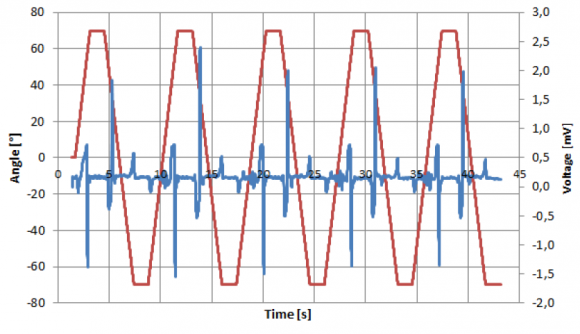
It looks like you're getting at least a 2nd-order highpass response to of the displacement there, and not the displacement itself, which is to be expected with a piezoelectric sensor. If you want absolute displacement you may not be able to get there from here.


