


Stairway to Thévenin
This article was inspired by a recent post on reddit asking for help on Thévenin and Norton equivalent circuits.
(With apologies to Mr. Thévenin, the rest of the e's that follow will remain unaccented.)
I still remember my introductory circuits class on the subject, roughly as follows:
(NOTE: Do not get scared of what you see in the rest of this section. We're going to point out the traditional approach for teaching linear equivalent circuits first. If you have light-headedness or dizzy spells, simply scroll down to the next horizontal rule.)
- Professor introduces Thevenin and Norton equivalent circuits. (see below)
- V = Vth - I * Rth. V = (In - I) * Rn. Rth = Rn. Vth = Rth * In. TH = Thevenin. N = Norton.
- Got it? Blah blah blah.
- Professor shows how to calculate Thevenin/Norton parameters by nodal analysis.
- Vague profound discussions of superposition, network analysis, reciprocity, etc.
- Professor goes through contrived examples of Thevenin and Norton equivalents.
- We have homework on contrived examples of Thevenin and Norton equivalents.
- We have exams on contrived examples of Thevenin and Norton equivalents.

(Circuit diagrams from Wikibooks)
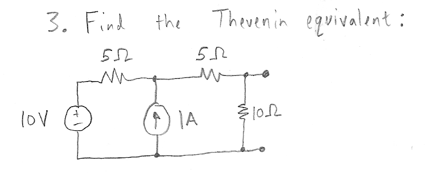
The contrived examples of Thevenin and Norton equivalents were always one of four types:
1. The basics. You get a Thevenin equivalent model, and you have to transform to a Norton model. (Or vice-versa.) If you get these wrong, you didn't listen to the lecture.

2. The five-minute problem. This one usually has a voltage source and a current source and two resistors in some weird configuration you would never see in real life. It's not too hard to solve. There, now you've done the work.
3. The tricky clever five minute problem. Here's where you start sweating. At least four or five sources and resistances, and the circuit looks vaguely like Picasso's "Guernica". Nobody could solve this in five minutes... oh, except look there, it's a trick, the answer doesn't depend on 95% of those nasty details.

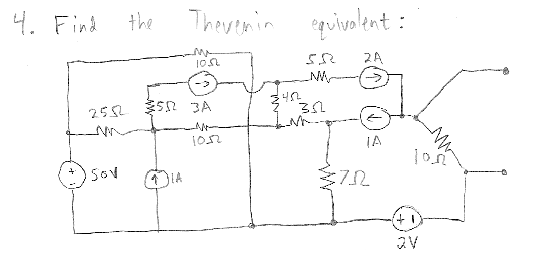
4. Circuits for masochists. Same kind of problem as #3, but without the clever escape hatch. Make sure you have plenty of pencil lead and paper.
[If you really want one of these, take the circuit above and short out the 2A current source. But don't expect me to figure out the answer. The answers for all the other problems are given at the end of this article.]
Whatever the level of difficulty, grin and bear it, and look forward to next semester.
So what was the point of learning that? Nobody uses Thevenin equivalents in real life, right?
Wrong.
Let's start over.
You find a small box. It has two metal tabs on it. Can't open it, can't see inside. On the box is a label that says:
TWO-TERMINAL LINEAR DEVICE: _______________
One of the boxes is checked, and the spaces are marked with information. It could be a battery, a humidity sensor, a voltage reference, a temperature sensor, a solar cell, a DC motor. Whatever.
You might have a use for this device. (Or not -- in which case, put it back.) If we're going to have any chance of doing so, we need to know what it is; we need to model it. Get out your digital multimeter.
- Measure the voltage V1 between the two tabs; that's one datapoint: open-circuit voltage = V1, current = 0.
- Find a small load (a current sink, a 100K load, something that isn't going to draw a lot of power given the open-circuit voltage), connect between the two tabs, and measure the voltage and current: voltage = V2, current = I2.
You have two data points. Sketch them on a graph. (Let's say V1 = 3.2V, V2 = 3.1V, I2 = 5mA) Draw a line through the two points. Why? Because the circuit is linear. Linear circuits have this nice property: multiply a change in current by some factor K (2, 3, 0.125, whatever), and you multiply a change in voltage by the same factor. On a graph, that forms a line.
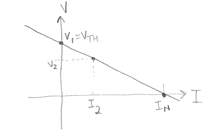
Oh, except we're not doing algebra problems with x and y, remember? We're talking about current and voltage, I and V: it's still a line, so aI + bV = c, where a, b, and c are some constants. Solve for V, collect terms, and you get the Thevenin equivalent:
V = Vth - I * Rth
Or you can solve for I, collect terms, and you get the Norton equivalent:
I = In - V * (1/Rn)
For our contrived set of measurements, V1 = 3.2V, I1 = 0, V2 = 3.1V, I2 = 5mA, we get Vth = V1 = 3.2V, Rth = Rn = -(V2 - V1) / (I2 - I1) = 0.1V / 5mA = 20 ohms. In = Vth / Rth = 160mA.
That's it. Thevenin and Norton models are artificial ways of empirically modeling a linear circuit, without knowing or caring what actual circuit elements might be involved. Thevenin models are a voltage source that droops with current, and Norton models are a current source that droops with voltage. Nothing special.
But again: who cares?
Here are three instances where Thevenin / Norton equivalents are useful.
1. Where the @#$@#% do I get a 2.000V reference?
You don't.
Well, that's not quite true. As far as I know, you can't get 2.000V standalone voltage reference ICs. Or 4.000V. You can, on the other hand, get 2.048V or 4.096V references quite easily, from any number of sources. They make these reference voltages available to stop embedded systems engineers who use analog-to-digital converters from complaining. 12-bit ADC + 4.096V reference = 1mV per ADC count. Hurray! Nice round numbers! Do we need them? No, but it sounds nice.*
Or if you really really want, you can buy some ADCs that have built-in 2.000V references. I wouldn't. (If you've got one anyway, I'd use it, but I wouldn't restrict my choice of ADC based on needing to have a built-in reference with nice round numbers.)
Or, you can just use a voltage divider: 4.096V is really close to 4.0V. If you use a 4.096V reference with 49.9 ohm and 2.10K 1% resistors, you get a voltage divider with an open-circuit voltage Vth = 4.001V and an output resistance Rth = 49.9 || 2100 = 48.7 ohms, and an extra quiescent current draw through the voltage divider of just under 2mA.
There's an added bonus here: It turns out that because the voltage divider ratio is so close to 1, the 1% resistors only add +/-0.045% voltage error (this number is very close to 1% * 2 / (2.10K / 49.9): the closer you get to a 1:1 input-to-output ratio, the smaller the effect the resistor tolerance is on the output voltage), much smaller than the voltage error of most commercially available voltage reference ICs.
That was a Thevenin model. Really.
We didn't use it to describe some contrived problem; instead, we used it to understand the effective open-circuit output voltage (4.001V) and resistance (48.7 ohms) provided by a voltage reference and a voltage divider.
Do we need an op-amp buffering the output? That depends. If you draw 1mA current, you'll cause the 4.001V to droop by 1mA * 48.7 ohms = 48.7mV, which is a lot for a reference. If you draw 1uA current, the droop is only 48.7uV, which isn't much. Once you have a simple model of the circuit, you can easily do the analysis and figure out if it matters in your application.
2. The quick and dirty low-pass filter
Let's say you have a 10K potentiometer with an RC low-pass filter. (Maybe the potentiometer is connected via long wires, or maybe instead of Vref as shown below, we're attenuating some input voltage that varies.)
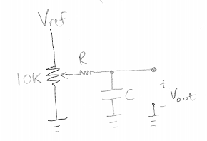
What should R and C be? Let's say I want a filter time constant of about 10msec (= 16Hz breakpoint frequency)
The output impedance of the wiper of the potentiometer is roughly between 0 (at the ends of travel; in reality slightly more than 0 because the wiper has nonzero resistance) and 2.5K (in the middle, where the potentiometer divides into two 5K halves on each side of the wiper, which in parallel offer a 2.5K output resistance).
If I use R = 10K, C = 1uF, I get a time constant between 10msec (wiper at the ends of travel) and 12.5msec (wiper right in the middle). If I don't care about a little variation, this might be fine.
Or I could use R = 100K, C = 0.1uF and get a time constant between 10msec and 10.25msec -- higher impedance compared to the potentiometer resistance, less variation.
All we cared about here was the Thevenin equivalent resistance; the equivalent voltage is proportional to the potentiometer rotation for a linear potentiometer, as expected.
3. Several sources hooked together
You have N sources of voltage connected in parallel through resistors. What's the output voltage?
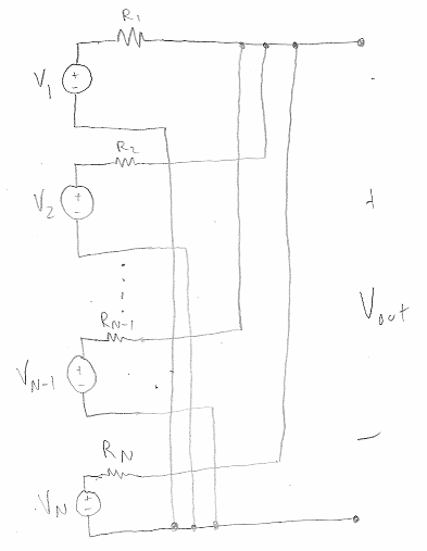
This one is hard to calculate through nodal analysis, but you can easily get it from Thevenin + Norton equivalents, if you transform all the circuits from their Thevenin equivalent to Norton equivalent:
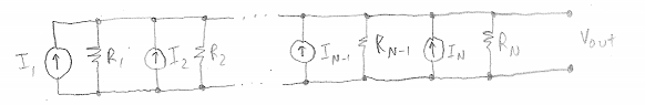
At this point, all the resistors are in parallel, as are all the current sources (which add together), so the net output voltage is given by the following elegant formula:
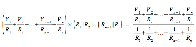
(I recently found out this is called Millman's Theorem.)
This isn't as contrived a situation as you might think. Suppose you have a circuit where a node connects to Vin through a 1K resistor, to Vref through a 10K resistor, and circuit ground through a 4.99K resistor. Then the node voltage is a direct application of this formula, yielding (Vref/10K + Vin/1K) / (1/1K + 1/10K + 1/4.99K) = (Vref/10 + Vin) * 0.7690.
So the next time you hear Thevenin or Norton equivalents, and cringe because you have flashbacks to your college classes, chill out and remember that they're useful tools in your mental toolbox. You're not going to run into a Guernica circuit unless you go out and find it yourself.
Happy New Year!
The answers for contrived problems 1-4 are:
- Vth = 4.0V, Rth = 400 ohms
- In = 20mA, Rn = 100 ohms
- Vth = 7.5V, Rth = 5 ohms
- Vth = 10V, Rth = 10 ohms (trick = current sources into 10 ohm resistor are equivalent to 1A current source in series with something; current sources in series with anything allow you to disregard the anything)
*There is one semi-legitimate use for quantized ADC readings that match the quantization of their human-readable representation. These are situations where 1 ADC count represents 0.1°C or 10mg or 2mm or 5mL or whatever, rather than 0.1357°C or 23.16mg or 1.578mm or 8.971mL. I call the first set of these "nicenumbers"; the second set is not. Furthermore, they are situations where not using "nicenumbers" for ADC quanta becomes awkward: in legal or commercial scenarios where the costs of rounding are significant, or if you just have lots of consumers that notice that your thermometer always jumps from 37°F to 38°F but then always skips to 40°F. On the other hand, I would argue two things: 1) that unless the measurement quantity is voltage, you can almost always change your sensor gain so that ADC quanta are nicenumbers, and 2) you really should never be counting on every last bit of ADC resolution being significant -- use oversampling and averaging to generate high-resolution measurements, and then round as necessary for human-readability.


- Comments
- Write a Comment Select to add a comment
To post reply to a comment, click on the 'reply' button attached to each comment. To post a new comment (not a reply to a comment) check out the 'Write a Comment' tab at the top of the comments.
Please login (on the right) if you already have an account on this platform.
Otherwise, please use this form to register (free) an join one of the largest online community for Electrical/Embedded/DSP/FPGA/ML engineers:


