


Interfacing with Electrochemical Gas Sensors
One of the most common forms of gas detector is based on an electrochemical sensor. This sensor creates a current (rather like a fuel cell) due to a redox reaction, usually with atmospheric oxygen. Almost any gas that can be persuaded to react with oxygen can be detected using such a sensor.
In operation, electrochemical gas sensors (in the usual three-terminal form) produce an output current at one of their terminals, referred to as the ‘working electrode’. This current can flow either out of or into the electrode, depending on the nature of the gas that the sensor is optimized for. This current is typically fed to the inverting input of an opamp connected up as a transimpedance amplifier, with a feedback resistor connected between the amplifier output and the inverting input. There may be additional components for modifying the frequency response and enhancing stability.
All opamps exhibit some amount of input current, due either to device bias or structural leakage or both. With any modern opamp built with CMOS technology, this current is very small in comparison with the sensor current under any normal conditions of operation. So this connection does not typically present a design problem for the sensor engineer in this configuration.
To ensure that the correct potential exists across the internal structure of the sensor, another of the terminals, called the ‘reference electrode’, has to be held at a predefined voltage difference (which may be zero, positive, or negative) with respect to the working electrode. This is usually achieved through a feedback connection in which a second opamp is used to drive the third and final terminal, known as the ‘counter electrode’, such that the reference electrode is held at the correct voltage.
This is all achieved using a classic and widely-known ‘potentiostat’ configuration (see Figure 1). This circuit can be found in numerous application notes and technical documents across the web, whether from sensor manufacturers, college electronics courses, or opamp manufacturers.
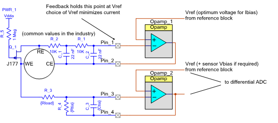
Figure 1: The classic ‘potentiostat’ electrochemical interface circuit
A few gas reactions require a ‘bias’ to be imposed between the working electrode (where the reaction takes place) and RE (the reference surface at which nothing is happening). This can be positive or negative, depending on the gas.
Now, the reference electrode has a rather different job to do compared to the working electrode. It is supposed to stay at the potential that the working electrode would be at if there was absolutely no gas reaction activity occurring. It’s constructed quite differently to the working electrode and is hidden away in the structure so that no gas can get to it. As a result, its impedance is very high, and its interface to the electrolyte in the sensor is dramatically affected if any significant current is allowed to flow at the reference electrode terminal.
This is the part of an electrochemical sensor interface circuit where you need to be more wary of amplifier input currents. It’s generally accepted that the current flowing at this electrode must be held to a nanoamp or less in order for conventional electrochemical sensors to suffer no short- or long-term degradation of their sensitivity or dynamic range.
Of course, every opamp manufacturer wants to convince you that only their product has the necessary low level of input current for success here. In practice, a wide range of CMOS technology amplifiers are suitable for this role. Input offset voltage is also something of a concern, but again, offset voltage differences of up to a millivolt between the two amplifiers in the circuit lead to errors typically much lower than the inherent variability from sensor to sensor.
In passing, note the JFET Q_1 connected between the working and reference electrodes, commonly found in this classic circuit. It’s there to protect the sensor. As they are like little batteries, electrochemical sensors tend to self-polarize. If the charge flowing from the redox reaction is not continuously swept away, it builds up within the working electrode. This can temporarily ‘poison’ the sensor, a process from which it might take several hours to recover. When the gas detector is running, the FET is held off by the strong positive gate bias. If the power fails for any reason, the JFET will conduct, preventing charge buildup on the electrodes. The FET is not fitted when the sensor needs to be biased for operation with the target gas type; in such cases, shorting WE and RE would actually exacerbate the problem.
Some additional care is needed at the system level, however, when designing electrochemical sensors made from single-chip mixed-signal processors. This is because the connection pins on such devices have been designed to service a wide range of applications. As a result, their internal circuit structures are quite complex, and some principles need to be followed in order that the current flows into or out of these terminals are maintained below the required constraints set by the electrochemical sensor.
Figure 2 shows the (typical, 85 oC) simulated input current at a GPIO pin of a programmable mixed-signal system-on-chip device, in this case the Cypress PSoC 4 Analog Coprocessor. A very similar curve will apply to all opamp equipped members of the PSoC 4 family of embedded processors.
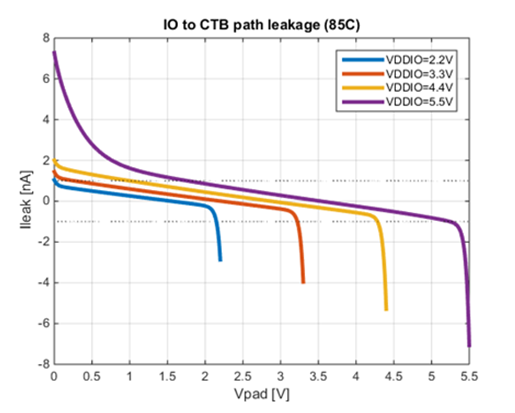
Figure 2: Simulations of the overall input current at a mixed-signal MCU’s GPIO pin
The set of curves in Figure 2 show the relationship between imposed input voltage and effective input current for a range of supply voltages. When the input is up near the positive rail (Vddio in the figure), a small current flows into the device’s terminal. When the input is down near the most negative voltage (Vss), which is at ground potential in a typical single-supply signal processing system, current flows out of the pin. As the supply voltage in use rises, the magnitude of the pin current for near-ground input voltages can increase to higher levels, especially for the highest permissible Vddio value.
Figure 3 shows some measured results of typical units at both room temperature and 85 oC for the 5.5 V supply voltage case, broadly agreeing with the simulated curves.
This behaviour is not primarily due to the input stage of the amplifier connected to the device pin but rather to the GPIO structure that’s also present, and that provides a robust input/output capability for both analog and digital signals. These general-purpose inputs require a significant level of ESD protection to ensure reliable operation in the field. The large MOS devices that form the output drive circuit are disabled when the pin is used as an analog input, but continue to do double duty as ESD clamp devices. Although they are ‘off’ in input mode, an effect rather beautifully termed “hot electron injection” allows a level of leakage current to flow under certain conditions. In the case of an electrochemical sensor reference electrode, this current may be a concern if the input voltages are not properly managed. The datasheet specifications for GPIO pin current are usually published for worst-case conditions that don’t reflect the specific usage in high impedance analog circuits. Thus, they can seem excessive when compared with dedicated discrete opamps.
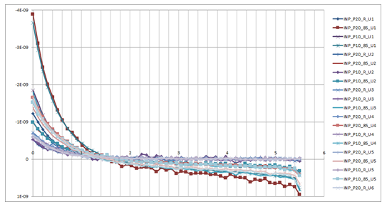
Figure 3: Some
measured input current results from a Cypress PSoC 4 embedded processor
A study of the figures shows that there is a usefully wide region in which the “hot electron currents” coming from the pull-up and pull-down branches of the GPIO cell cancel out. This is where the family of curves crosses the x-axis, i.e. the zero total current line. The cancellation is broadly stable with temperature and process. If the circuit voltages lie within this range, the pin structure is able to deliver the required low level of input current for an electrochemical sensor application.
What impact does this have on the design of an electrochemical interface circuit with such an integrated device? Fortunately, very little. The voltage at the reference electrode is set by the potential applied to the non-inverting terminal of the opamp that’s driving the counter-electrode. Setting that potential somewhere close to half the supply voltage would normally be the natural choice of most designers working with single-supply analog circuits. For many of the gases that are sensed in this way, the bias voltage required between the reference and working electrodes is zero, meaning that the non-inverting input of the transimpedance amplifier is also connected to the supply midpoint. For such gases, the configuration is now complete, and the designer is assured of a sufficiently low level of input current for typical electrochemical gas sensors.
Some gas types require a bias voltage between working and reference electrodes; it’s rarely as much as a volt in either direction, and generally applied to reduce the sensitivity to another gas. To achieve this, the voltage applied to one of the opamp non-inverting terminals can be adjusted, while still maintaining the sub-nanoamp current requirement at the reference electrode.
In a modern analog-focused mixed-signal device such as the Cypress PSoC 4 Analog Coprocessor, the necessary reference voltages can be programmed internally without the need for external support components.
As Figure 2 shows, significantly lower input currents can be achieved if the supply voltage of the system is limited to 4.4 Volts or less, in the case with the PSoC family of embedded processors used as examples here. This is readily achieved across a wide range of battery chemistries. When supply voltage and reference voltage are chosen well, it’s clear that effective electrochemical sensor interfacing with sub-nanoamp input currents is possible.
Author
For nearly four decades, Kendall Castor-Perry has been chasing signals through electronic systems, wringing out the information they are hiding. He’s a world-class authority on filters and precision analog circuit engineering and a tireless champion of the needs of the customer. He has been widely published and syndicated, especially when sharing his extensive filtering knowledge as “The Filter Wizard.” He has a BA in Physics from Oxford and an MBA in MBA stuff from London Business School. Kendall is currently Senior MTS Architect in Cypress Semiconductor’s Programmable Systems Division, pushing on the performance:power:price boundaries constraining tomorrow’s critical sensor-processing systems.


- Comments
- Write a Comment Select to add a comment
To post reply to a comment, click on the 'reply' button attached to each comment. To post a new comment (not a reply to a comment) check out the 'Write a Comment' tab at the top of the comments.
Please login (on the right) if you already have an account on this platform.
Otherwise, please use this form to register (free) an join one of the largest online community for Electrical/Embedded/DSP/FPGA/ML engineers:


