


Isolated Sigma-Delta Modulators, Rah Rah Rah!
I recently faced a little "asterisk" problem, which looks like it can be solved with some interesting ICs.
I needed to plan out some test instrumentation to capture voltage and current information over a short period of time. Nothing too fancy, 10 or 20kHz sampling rate, about a half-dozen channels sampled simultaneously or near simultaneously, for maybe 5 or 10 seconds.
Here's the "asterisk": Oh, by the way, because the system in question was tied to the AC mains, I needed some voltage isolation.
Without isolation, a working solution would probably cost in the $200-$450 range. With isolation it probably pushes the cost an order of magnitude to $2000-$4500. There is always the possibility of pushing the isolation on the other side of the ADC: instead of analog isolation, using a non-isolated USB data acquisition system with an isolated USB adapter; that adds $50-$150 extra in cost... but all the signals in question would have to be referenced to about the same potential, and they aren't in this case.
Analog isolation is a pain. There aren't many options; you can use one of these dual-feedback optoisolator modules like the Avago HCNR201 or the modulation/demodulation style like the TI ISO124.
While looking for a solution, I ran across a handful of ICs from a few manufacturers that look like they might do the trick. These are sigma-delta modulators (sometimes called delta-sigma modulators):
- Avago ACPL-C797 -- ±200mV range, 10MHz internal clock
- Avago ACPL-796J -- ±200mV range, 20MHz external clock
- Avago HCPL-7560 -- ±200mV range, 10MHz internal clock
- Avago HCPL-7860 -- ±200mV range, 10MHz internal clock
- Avago HCPL-786J -- ±200mV range, 10MHz internal clock
- Texas Instruments AMC1203 -- ±280mV range, 10MHz internal clock
- Texas Instruments AMC1204 -- ±250mV range, 20MHz external clock
- Analog Devices AD7400A -- ±250mV range, 10MHz interal clock
- Analog Devices AD7401A -- ±250mV range, 20MHz external clock
These are remarkably similar in specifications, and I'm not sure who came out with the first of these chips (probably Agilent with the HCPL-7560 before they spun off the former Hewlett-Packard optoelectronics division into Avago; since then Avago has changed the part numbering from HCPL to ACPL). You stick an analog 5V power supply on the isolated side, along with your input signal, and on the other side you power the IC and get a data stream output, along with either a clock recovery output or a clock input. From the viewpoint of designing them into a high-volume product, they're kind of expensive (compared to simpler ADCs which use successive approximation registers), at $3-$5 each in large quantities; for test instrumentation, at $6-$10 each in small quantities, they're a lot less expensive than other solutions.
So what's a sigma-delta modulator?
Sigma-delta: the power of avoiding the "I Want It Now" approach to ADC
You've probably heard of sigma-delta analog-to-digital converters. These have been around for a while, especially in the above-16-bit market for ADCs. Historically they were used for very slow but very precise measurements: the classic application is strain gage digitization for weigh scales. Now you can buy 24-bit ADCs from several manufacturers and they have built-in 50/60Hz notch rejection.
Unlike the Successive Approximation Register (SAR) and Flash types of ADCs, both of which have sample-and-hold inputs (the "I want it now!" approach), sigma-delta converters do things a little differently. These converters have two parts (no, they're not "sigma" and "delta"):
- a modulator, which takes an analog voltage and creates a fast stream of low-resolution (usually 1-bit) ADC samples to oversample the input waveform
- a filter, which takes the fast low-resolution ADC samples, and filters and decimates them to generate a lower speed stream of high-resolution ADC samples.
I wouldn't be able to do justice to explaining the way these work in detail; for that, I would recommend a number of references (see the end of this blog article) but especially the MT022 tutorial on sigma-delta conversion from the legendary Analog Devices engineer Walt Kester, who has been at ADI since 1969.
Here's the essence of the idea: Analog-to-digital conversion can be seen as conversion of a continuously-varying signal to one that has discrete levels, and this process can be viewed as adding quantization "noise" (the difference between the continuous input and the discrete-leveled output). Sigma-delta conversion pushes this noise "away" from the signal by both oversampling, where the quantization noise smears out over a larger spectrum, and "noise shaping", which biases the noise into the high-frequency portion of the data and keeps it mostly out of the low-frequency portion of the data -- which is where the signal you care about resides. Then the filtering part of the sigma-delta converter can remove the bulk of the quantization noise.
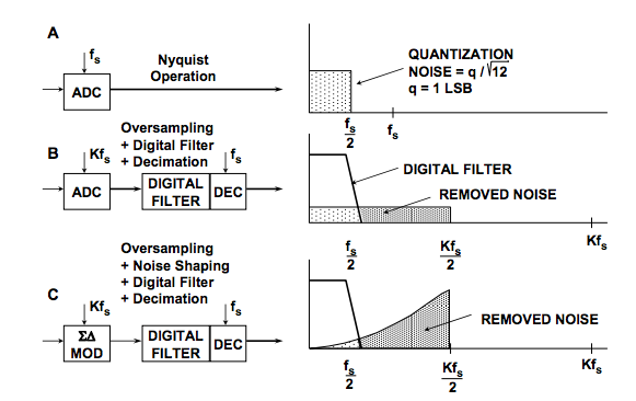
(Figures from Analog Devices MT-022.)
To do the noise shaping, it takes a sigma-delta modulator. Here's what a second-order sigma-delta modulator looks like:
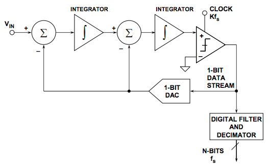
If you want to know how it works to cause noise shaping, you'll have to read some of the references in detail and get into frequency-domain analysis and what-not.
The key features of a sigma-delta modulator are this:
- It's a 1-bit ADC which is really fast and really accurate at low frequencies compared to the clock rate. (That is -- you don't look at each individual bit of the output, you look at the bitstream and examine the density of 1s via low-pass-filtering.)
- It's an integrating converter -- you don't sample the input at a particular instant; instead the input voltage continuously has an effect on the digitization.
- You get enhanced effective bit accuracy for oversampling. For a "regular" ADC, each time you double the sample rate and average the results, you get another 1/2 bit of effective resolution. (For twice the resolution you need 4x the sample rate.) With a 1st-order sigma-delta modulator, because of the noise shaping, if you double the sample rate, you get another 3/2 bits of effective resolution. (For twice the resolution you only need to increase sampling frequency by a factor of 2(2/3) = 1.59) With a 2nd-order sigma-modulator, if you double the sample rate, you get another 5/2 bits of effective resolution. (For twice the resolution you only need to increase sampling frequency by a factor of 2(2/5) = 1.32)
Here we get to the good parts.
With a sampling ADC, you have to decide when to sample, and hope that your input doesn't have much noise around those sampling instants, and that it doesn't have much ripple content above the Nyquist frequency (half the sampling frequency) where it can fool the ADC into giving the wrong results. With a sigma-delta ADC, you don't really need to worry about that, for two reasons: one is that the ADC bit rate is so high that you can use a really cheap RC filter to get rid of ultra-high frequency content, and the other is that even if some high-frequency noise gets through, it will be averaged out by the input integrator.
And if the sigma-delta clock rate is synchronized to a multiple of another system source, like a PWM signal or a current waveform with ripple at the PWM frequency, then you can get rid of this ripple altogether and read just the average value of the input. Which is great for power electronics.
That's the good part of the integrator. The fact that it's a 1-bit ADC which puts out a stream of digital bits, means we only need 1 digital isolation channel if we want to get the ADC across an isolation barrier, along with a 2nd channel for clock input or clock recovery, and we don't need to handle a SPI protocol (when combined with an isolation barrier, this means worrying about bit timing and round-trip latency and all that); the bits just come along and you deal with them one by one by one.
Filtering and downsampling
So it's a no-brainer!.... except for one thing. How do you deal with a 10-20MHz stream of digital bits? I mean, come on, information overload!
Well, here's the hard part, then. If you're doing real-time control, this is fast enough that you'd better be using a dedicated sigma-delta filter/decimator, or be good with FPGA programming. The theory behind filtering and downsampling is actually pretty easy. A lot of applications use 3rd-order sinc filters, also known as cascaded integrator-comb filters. These are great for digital applications. There's no multiplies involved, just adds, subtracts, and single-step delays.
You basically do this on the input side, at a fast rate:
sum1 += input
sum2 += sum1
sum3 += sum2
and then on the output side at a submultiple of the fast rate, every N iterations:
diff3 = sum3 - sum3_prev
sum3_prev = sum3
diff2 = diff3 - diff3_prev
diff3_prev = diff3
output = diff2 - diff2_prev
diff2_prev = diff2
This gives you a low-pass filtering along with a decimation automatically, and a scaling factor of Nk where k is the number of sections in the comb filter. (3 in the above example.)
What I do wish, is that there were some data acquisition systems that took in sigma-delta bitstreams and handled the filtering/decimation and acquired the results into memory on your PC. Sigma-delta ADCs are nice, but it's much more powerful (and gives you the ability to use simple 1-bit digital isolation) when you can use a sigma-delta modulator and combine it with a separate filter/decimator that lets you choose what clock to use, how fast to oversample it, etc.
In any case, things have been improving over the years, and I look forward to one day being able to use sigma-delta converters not only for instrumentation, but for embedded control as well.
Happy converting!
References:
MT-022 ADC Architectures III: Sigma-Delta ADC Basics -- Walt Kester, Analog Devices
MT-023 ADC Architectures IV: Sigma-Delta ADC Advanced Concepts and Applications -- Walt Kester, Analog Devices
How delta-sigma ADCs work, part 1 -- Bonnie Baker, Texas Instruments
How delta-sigma ADCs work, part 2 -- Bonnie Baker, Texas Instruments
p.s. I haven't forgotten about the second part of How to Estimate Encoder Velocity Without Making Stupid Mistakes, which will cover PLLs and observers; my life has been really busy lately, and to do this topic justice I probably won't get enough time to finish it until later this year. Stay tuned!


- Comments
- Write a Comment Select to add a comment
To post reply to a comment, click on the 'reply' button attached to each comment. To post a new comment (not a reply to a comment) check out the 'Write a Comment' tab at the top of the comments.
Please login (on the right) if you already have an account on this platform.
Otherwise, please use this form to register (free) an join one of the largest online community for Electrical/Embedded/DSP/FPGA/ML engineers:


